औद्योगिक ऊष्मा पुनर्प्राप्ति बॉक्स एक सघन और कुशल प्रणाली है जिसे विभिन्न औद्योगिक अनुप्रयोगों में अपशिष्ट गैस धाराओं से ऊष्मा पुनर्प्राप्ति के लिए डिज़ाइन किया गया है। यह गैस-से-गैस ऊष्मा एक्सचेंजर का उपयोग करके गर्म निकास गैसों से ऊष्मा ऊर्जा को आने वाली ताज़ी हवा में स्थानांतरित करता है, बिना दोनों वायु धाराओं को मिलाए। यह प्रक्रिया अतिरिक्त तापन की आवश्यकता को कम करके ऊर्जा दक्षता में उल्लेखनीय सुधार करती है, जिससे परिचालन लागत कम होती है और पर्यावरणीय प्रभाव कम होता है।
एल्युमीनियम या स्टेनलेस स्टील जैसी टिकाऊ सामग्रियों से निर्मित, यह प्रणाली उच्च तापमान और संक्षारक वातावरण को सहन करने में सक्षम है। आंतरिक ताप विनिमायक, जो अक्सर एल्युमीनियम फ़ॉइल या प्लेटों से बना होता है, उच्च तापीय चालकता और कुशल ऊष्मा स्थानांतरण सुनिश्चित करता है। यह डिज़ाइन गंदी निकास हवा और स्वच्छ आपूर्ति हवा के बीच परस्पर संदूषण को रोकता है, जिससे यह खाद्य प्रसंस्करण, तंबाकू, मुद्रण, रसायन और कीचड़ उपचार जैसे उद्योगों के लिए उपयुक्त है।
यह ऊर्जा-बचत समाधान न केवल अपशिष्ट ऊष्मा को पुनः प्राप्त करता है, बल्कि आंतरिक वायु गुणवत्ता में सुधार और स्थिर उत्पादन वातावरण बनाए रखने में भी मदद करता है। स्थापित करने और रखरखाव में आसान, औद्योगिक ऊष्मा पुनर्प्राप्ति बॉक्स उन कारखानों के लिए एक स्मार्ट विकल्प है जो स्थिरता को बढ़ाना और ऊर्जा-बचत नियमों का पालन करना चाहते हैं।
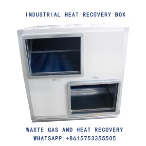
औद्योगिक ताप वसूली बॉक्स, अपशिष्ट गैस और ताप वसूली, गैस से गैस ताप एक्सचेंजर