산업용 열 회수 장치는 다양한 산업 분야에서 폐가스 흐름으로부터 열을 회수하도록 설계된 작고 효율적인 시스템입니다. 가스-가스 열교환기를 사용하여 두 기류를 혼합하지 않고 고온의 배기 가스에서 유입되는 신선한 공기로 열에너지를 전달합니다. 이 공정은 추가 가열 필요성을 줄여 에너지 효율을 크게 향상시키고, 운영 비용과 환경 영향을 줄입니다.
알루미늄이나 스테인리스 스틸과 같은 내구성 있는 소재로 제작된 이 시스템은 고온 및 부식성 환경을 견딜 수 있습니다. 내부 열교환기는 주로 알루미늄 호일이나 판으로 제작되어 높은 열전도도와 효율적인 열 전달을 보장합니다. 이러한 설계는 오염된 배기 공기와 깨끗한 공급 공기 간의 교차 오염을 방지하여 식품 가공, 담배, 인쇄, 화학, 슬러지 처리 등의 산업에 적합합니다.
이 에너지 절약 솔루션은 폐열을 회수할 뿐만 아니라 실내 공기질을 개선하고 안정적인 생산 환경을 유지하는 데에도 도움을 줍니다. 설치 및 유지 보수가 간편한 산업용 열 회수 박스는 지속 가능성을 높이고 에너지 절약 규정을 준수하려는 공장에 현명한 선택입니다.
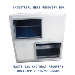
산업용 열 회수 상자, 폐가스 및 열 회수, 가스-가스 열교환기